While working on our training material for the Offensive IoT Exploitation course, we here at Attify did a ton of in-depth research into all the possible aspects of IoT devices. One of the component that we focused primarily, in radio based exploitation was Zigbee Security, which is arguably the most popular IoT radio communication protocol in Smart Homes and Medical Devices.
Introduction to Zigbee
Zigbee is one of the most common communication protocol found in Smart Home devices and several other categories of IoT devices. The extremely power efficient nature, mesh networking and ease of usage makes Zigbee one of the popular choice among manufacturers.
It’s a specification built on top of the IEEE 802.15.4, and an open protocol created by the member companies of Zigbee Alliance, which include companies like TI, Silicon Labs, Philips and many others.
There have been a number of iterations of the Zigbee protocol, the most recent at the time of writing being Zigbee 3.0.
Attacks possible
Zigbee being a radio communication protocol suffers from the standard radio based vulnerabilities. Some of the attacks that are possible in Zigbee communications are :
- Attackers being able to sniff the data being transmitted
- Replaying of packets after capturing it to perform malicious actions
- Sniffing of the encryption key during the initial communication
- Modification of the captured packets and then replaying
- Spoofing based attacks
- Denial of Service situations
This blog post is an introductory guide to set things up in case you would like to learn Zigbee exploitation on your own and perform additional exploitation of each of the vulnerabilities mentioned above.
Hardware Required
Before reading the hardware required section, bear in mind that this is one of the possible combination you could use to get started with Zigbee Security. There could be innumerable types of hardware you could use – such as using a Zigbee dev kit, using a commercial IoT device emitting Zigbee signals and so on.
Below is a simple setup which you can get started with:
- Arduino Uno/Nano
- DigiKey Xbee module / Arduino Xbee shield
- Atmel RzRaven USB stick
- Attify Badge
Arduino : Arduino is the de-facto to get started into any sort of electronics projects. Chances are high that you might have used this in your university or high school. The Nano is the most smallest Arduino nano, but sufficient enough for our purposes.
DigiKey Xbee module / Xbee Shield : In order to learn Zigbee, you need something which can transmit and receive Zigbee signals. Xbee is a full duplex transceiver capable of wirelessly communicating with other Xbee modules using Zigbee standard protocol.
Atmel RzRaven USB Stick: This is the half-duplex module which performs the “magic” of sniffing and transmitting modified captured Zigbee packets. If you’re familiar with other sort of radio exploitation, consider this as the “HackRF for Zigbee”.
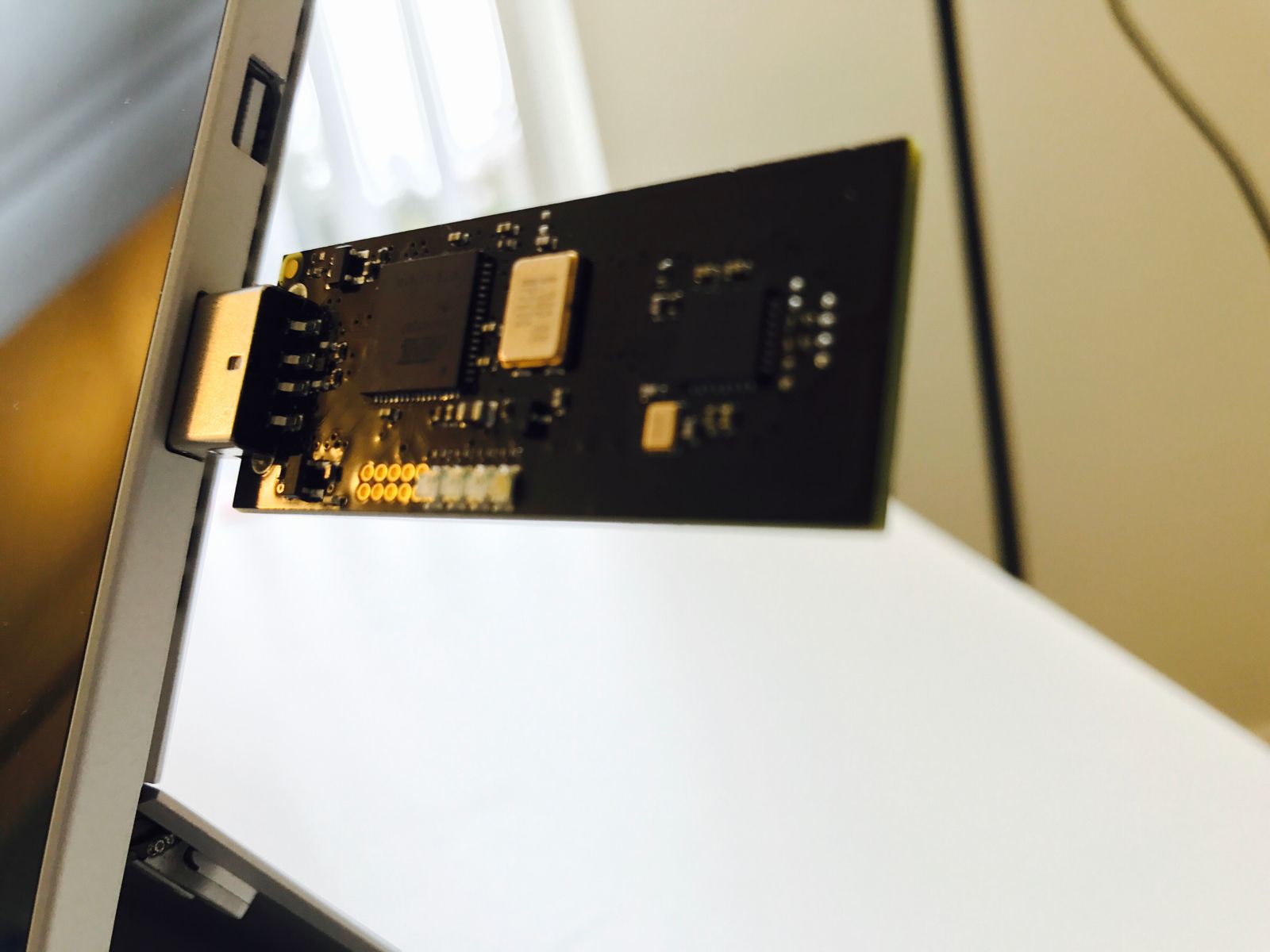
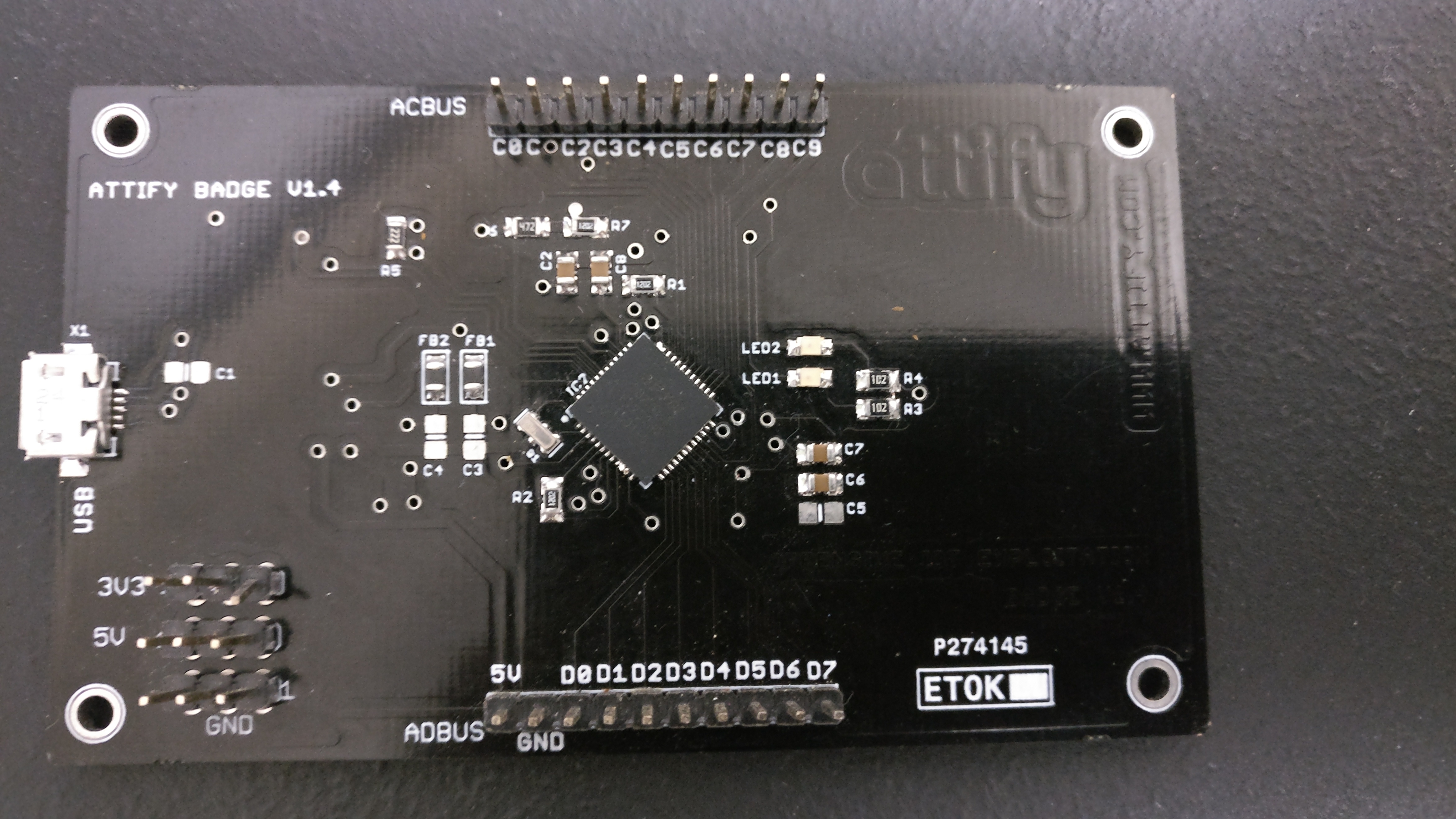
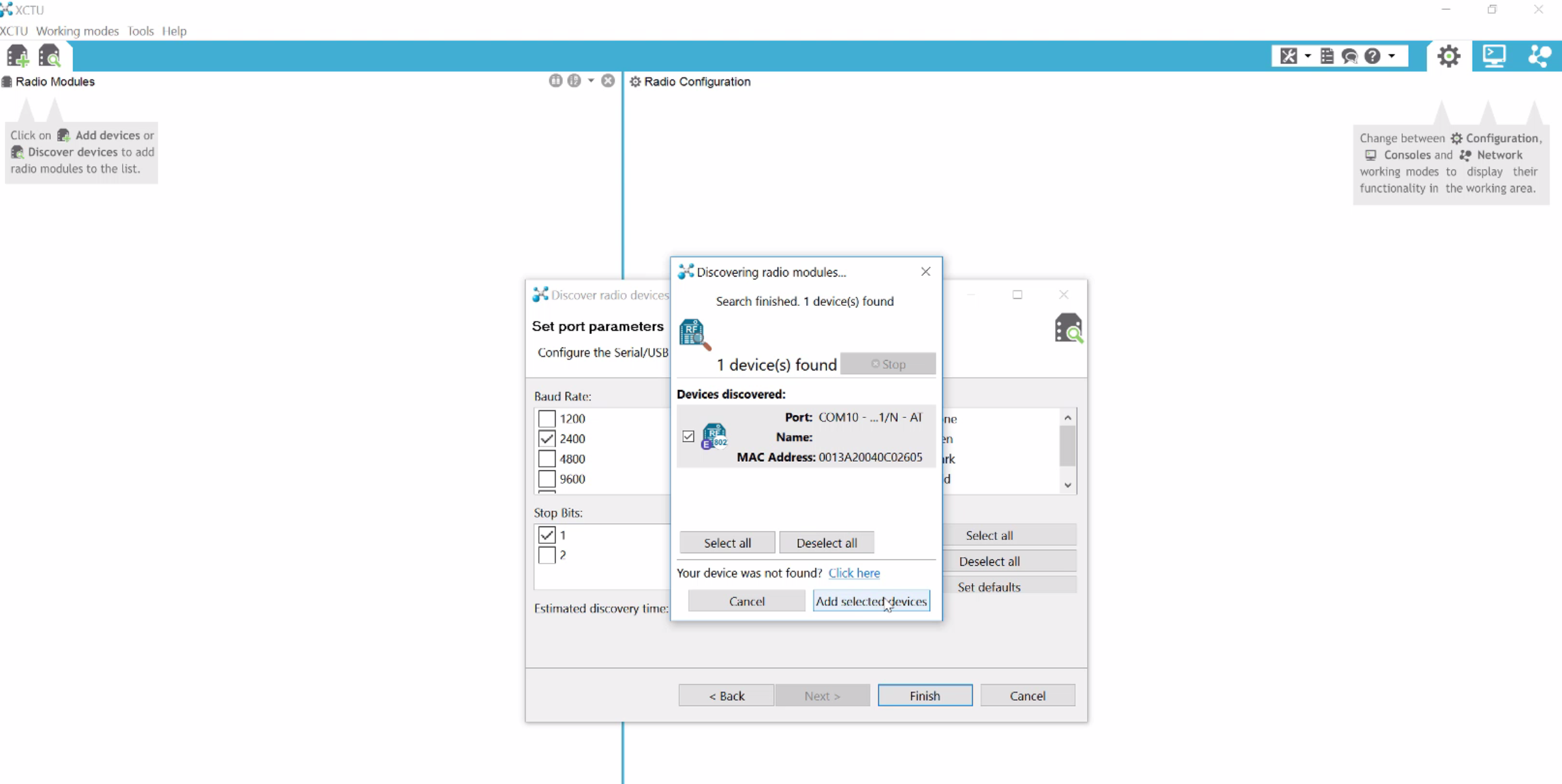
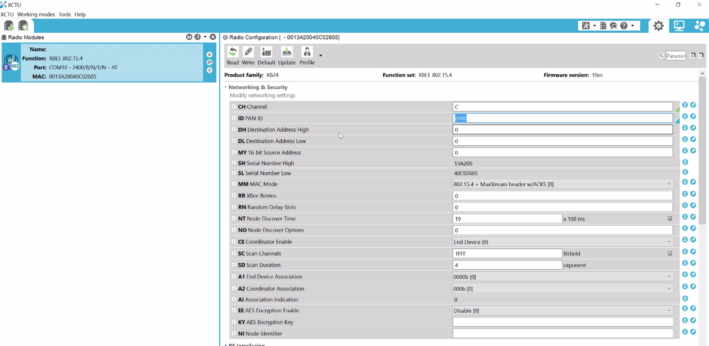
Attify Badge: You can use this to program the Xbee module with XCTU and plugging in the badge on your system. This is because Xbee usually doesn’t have the miniUSB or similar port which could be used to directly plug it in and program. In case you don’t have Attify Badge or similar hardware, head out to Amazon or your local store and order a mini USB kit for Xbee – something like this.
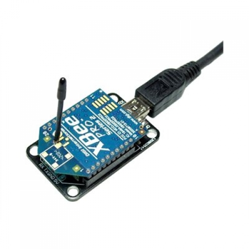 MiniUSB board for Xbee (img src : robosavvy.com)
Or you can order by emailing us here
Hacking IoT Embedded devices with Attify
Programming Arduino and Xbee
Programming Arduino
In order to program Arduino, simply download and open up the Arduino IDE from here https://www.arduino.cc/en/Main/Software . Once loaded, open up the Hub and node programs from the Attify’s github repo to each of the Arduino one after the other.
The code has been detailed with inline comments to help you understand what the code means.On an additional note, the code sample provided also takes the temperature, humidity and light values via the sensors and uses the DHT library. It is perfectly fine in case you decide to do the entire analysis and exploitation with a hardcoded string being transmitted, instead of the DHT values. Or, if you would like to use the code as it is, make sure to buy the DHT11 and additional required devices that go along with it.
Tools needed
- Arduino * 1 https://www.sparkfun.com/products/11021
- DHT 11 * 1 https://www.adafruit.com/product/386
- XBee S1 module(Different configuration needed for S2 module) * 2
- LDR/Photocell * 1 https://www.sparkfun.com/products/9088
- BC547 *1 https://www.sparkfun.com/products/8928
- LED * any number https://www.sparkfun.com/products/10635
- Jumper cables https://www.sparkfun.com/products/13870
- Breadboard https://www.sparkfun.com/products/12046
- Xbee shield * 2 https://www.sparkfun.com/products/12847
Schematics
Node code :
// Offensive IoT Exploitation by Attify // www.attify.com | www.offensiveiotexploitation.com // secure@attify.com #include <dht.h> //Library for DHT11 Humidity #define dht_dpin A0 // DTH11 Data pin connected to AO of arduino #define led 2 // Led connected to Pin D2 #define ldr A1 // LDR connected to Pin A1 dht DHT; // Creating DHT function void setup() { // initialize serial: Serial.begin(2400); // Initiliaze Hardware serial for xbee pinMode(2, OUTPUT); // Pin direction of LED to Output as it sends current } void loop() { // Continous loop // if there's any serial available, read it: DHT.read11(dht_dpin); // Reading DHT11 using the library int lig = analogRead(ldr); // Reading analog values from LDR int ligp = map(lig, 0, 1023, 0, 100); // Mapping the 10bit resolution ADC to 0 to 100 int h = DHT.humidity; // Humidity value int t = DHT.temperature; // Temperature value while (Serial.available() > 0) { // Checking for any data on Xbee int red = Serial.parseInt(); // look for the next valid integer in the incoming serial stream if (Serial.read() == '!') // Check if the next Serial data is '!' { if(red == 1) // if the recieved data is 1! { Serial.print(h,DEC); // Send humidity value with '!' Serial.print("!"); } else if(red == 2) // if the recieved data is 2! { Serial.print(t,DEC); // Send Temperature value with '!' Serial.print("!"); } else if(red == 3) // if the recieved data is 3! { Serial.print(ligp,DEC); // Send Light value with '!' Serial.print("!"); } else if(red == 4) // if the recieved data is 4! { digitalWrite(2, HIGH); // Turn ON the LED delay(100); } else if(red == 5) // if the recieved data is 5! { digitalWrite(2, LOW); //Turn OFF the LEd delay(100); Serial.print("!attify!"); // Send the AES key } } } }
Hub code :
// Offensive IoT Exploitation by Attify // www.attify.com | www.offensiveiotexploitation.com // secure@attify.com #include <SoftwareSerial.h> // Software based UART port to use Zigbee module int a = 1; float hum = 0, temp = 0; // Float Variable to store Temperature and Humidity SoftwareSerial xbee(3, 2); // RX, TX void setup() //One time preloading function { Serial.begin(9600); // Hardware Serial initialization to be connected to a bluetooth module or PC xbee.begin(2400); // Software Serial initialization at 2400 Baud rate to communicate with zigbee } void loop() // Continous loop { xbee.print(a); // Sends (a) with "!" to Xbee -> "1!" Requests temperature data and vice versa xbee.println("!"); while(xbee.available() > 0) //Checks is any data has been recieved from zigbee. { char aChar = xbee.read(); //reading the value from the Xbee serial port if(aChar == 33) //If the first character is 33 ie) ! in ASCII { xbee.flush(); // Clear the buffer and aChar = NULL; } if(aChar >= 100) // If it is more than 100 or random ASCII character flush the data { xbee.flush(); aChar = NULL; } Serial.print(aChar); //Printing the Read value } if(a == 3) // if a = 3 create new line or end of one set of data transmission { Serial.println(); //New line print } else { Serial.print(","); // if a not 3 then add "," } if(a> 3) // after a > 3 print the AES encryted data to xbee { a =1; // initialize a = 1 back xbee.print("!f+F8YW+9W3+Cg0S1NVBexycQxz32biWTmzVsxO48+fk=!"); } delay(100); // Wait for few ms for this to happen xbee.flush(); // flush any data in Xbee serial port a=a+1; //Increment data if(Serial.available()); // Check if any data is sent from Hardware serial port { int r = Serial.parseInt(); // Recieving any integer data if(r== 1) // if recieved data is 1. Send 4! which turns the LED on the Node. { xbee.print(4); xbee.print("!"); delay(100); } if(r== 2)// if recieved data is 2. Send 5! which turns the LED off the Node. { xbee.print(5); xbee.print("!"); } } }
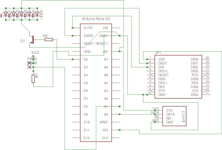
Also below are the schematics in case you want to build an exact similar setup as our starting kit :
Node Schematics:
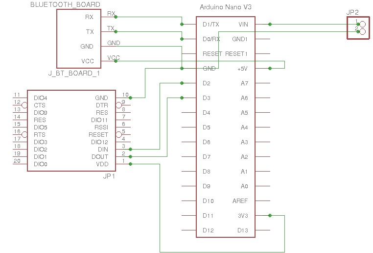
Node Schematics for Zigbee vulnerable setup
Hub Schematics
Hub Schematics for Zigbee vulnerable setup
