
Introduction
This is Part 1 of a three-part blog post that will look to describe what a bootloader is and where it fits into the boot process.
Part 2 will describe the U-Boot bootloader, specifically "Das U-Boot", where we will be further examining its origins and its usage in the world of embedded Linux systems.
With a thorough understanding under our belt, we will look to examine the possible attack vectors available using practical examples in Part 3.
What is a Bootloader
In an embedded system context, the bootloader is simply the part of the system that is used at start-up to assist in the process of successfully starting the system and loading the operating system kernel.
The Bootloaders Role
In an embedded system the bootloader has two main functions:
1. Initialization of the System
2. Loading of the Kernel
An embedded system would be in an absolute minimal functional state, just after power-on or reset. In this state, many controllers and/or supporting chipsets would not yet have come online, and as such, there is a requirement to pre-empt this functionality using available resources.
Typically this initial functionality is handled by on-chip static memory (ROM). This type of bootstrapping from ROM requires the system to usher in further phases before the final operational state is achieved.
The final operational state occurs when the kernel has finally been loaded into RAM and is executed. Once this state has been achieved the bootloader is no longer required and the memory that was previously allocated is reclaimed and reused by the system.
The 3 phases of the boot sequence
Phase 1: ROM Code
As previously mentioned, based on the minimalistic supporting controllers and/or chipsets, the code executed after a power-on or reset is typically stored on-chip on the SoC. This code is known as ROM Code and is loaded onto the chip upon manufacturing.
The ROM Code itself is tasked with loading the next instructions or chunk of code into SRAM using a choice of peripheral devices. The main reason that SRAM is used is due to this type of memory NOT requiring a memory controller to function and can thus be utilized prior to any sort of controller initialization.
Some examples of peripheral devices that ROM Code can choose from are:
- NAND memory
- Flash memory connected through SPI
- MMC
In most cases, the boot sequence, as executed by the ROM Code, will fall back to a number of possible other sources, such as:
- Ethernet
- USB
- UART
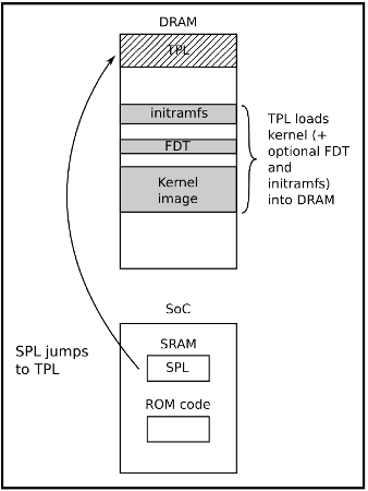
In some cases, the SRAM capacity is not large enough to support a full bootloader and in these cases, an SPL (Secondary Program Loader) is used. This SPL itself is loaded into SRAM and at the very end of the ROM Code phase, the SPL is found at the start of SRAM and continues on where the ROM Code left off.
Phase 2: SPL (Secondary Program Loader)
The SPL’s main job is the loading of a TPL (Tertiary Program Loader) into DRAM. Once loaded into DRAM the TPL then takes on where the SPL left off, however this time from Dynamic memory.
This process allows for an ever-increasing availability of memory which is used to allocate to the execution of the kernel and file system.
Phase 3: TPL (Tertiary Program Loader)
The TPL typically takes the form of a fully-fledged bootloader, such as U-Boot, which allows for an interactive prompt. This interactive prompt allows for user input in order to run various commands, some of which are:
- The loading of new boot images into flash storage
- Execution of memory and storage management tasks
Once this phase has been completed the kernel is typically located in memory and execution is then passed to it via the bootloader.
Bootloader to Kernel
Typically before passing full control to the kernel the bootloader needs to offload details by providing plain information to the kernel in order that the kernel can execute cleanly. The following information is typically passed to the kernel by the bootloader:
- The type of SoC used
- The size and location of RAM and CPU speed
- The Kernel Command Line
- The location and size of the DTB (Device Tree Binary), this is optional and is dependent on whether the device support DTB
- The location and size of the initial RAM disk (initramfs), this is also optional and is dependent on whether the File System itself will be offered up as an initial RAM disk or not
This information in most modern ARM architectures is typically passed to the kernel using a Device Tree.
Device Trees
A device tree is merely a structured attempt at describing an underlying computer system, such that, a Linux kernel can gain insight into the under-the-hood components of the system that it is running on.
As its namesake implies the details that are described the system are structured in a tree-like fashion, with the root of the tree (Root Node), denoted as a slash ‘/’. All subsequent nodes in the tree are further denoted using a name, value property e.g. name = ‘value’
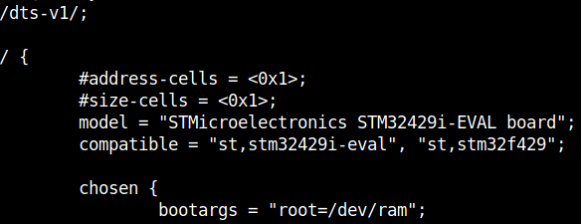
In order for the device tree to be usable by the bootloader and kernel, it must be presented to both the bootloader and the kernel as a binary file. The Device-Tree-Compiler (DTC) is used to compile a .dts source into a .dtb binary for presentation to both of the interfaces.
Stay tuned for Part 2 "Das U-Boot" ...