
Welcome to another blog post by Attify – your source for all security and pentesting tips and techniques for IoT devices and mobile applications.
In this post, we would like to introduce you to the **Attify Badge Tool **– which works as a companion app to Attify Badge, which is a hardware device used to hack IoT devices and perform Hardware and Embedded device exploitation.
Hack IoT devices with the Attify Badge Tool
Why a tool for IoT Hardware Exploitation
So many times we have seen people who want to start into IoT security being confused about what kind of hardware setup they need or what hardware tool they need in order to interact with the devices. If they find a hardware device, it’s often not user-friendly or the installation of the required libraries is extremely painful.
The idea behind building the Attify Badge Tool is to create a tool which would be useful for both security researchers and IoT enthusiasts who would like to get started in IoT security to perform Hardware and Embedded Device Exploitation.
Speaking at a very general level, instead of reinventing the wheel – we used a collection of open source libraries and tools and wrapped them in an extremely easy to use application with a nice Graphical Interface.
Attify Badge and Attify Badge tool makes IoT device exploitation extremely easy for anyone who wants to get started with the Internet of Things Security.
For a much deeper insight on how to use the badge, you can go through this easy to follow post which we have written over here for you.
Video Demo
Usage
The Attify Badge Tool is comprised of 5 main modules corresponding to the 5 protocols supported by the Attify Badge that are:
- UART
- SPI
- JTAG
- I2C
- GPIO
So if your target device which you are trying to exploit has any of these interfaces, Attify Badge should be your go-to tool for that purpose.
The main aim of this blog post is to cover the details and usage of each module, so that once you start your IoT Exploitation journey – you can follow these to make sure you succeed.
So let’s get started. In case you would like to apply all of these techniques in real-world scenarios, consider getting our IoT Exploitation kit or sign up for our next training class.
1. UART
UART is one of the most popular communication protocol in Embedded Devices. It is the protocol which if found, can at occasions give you a direct root shell without authentication.
Even though you have a number of tools such as Baudrate.py, Screen, minicom etc., how many tools are you going to use! Rather use a single tool for the entire Hardware exploitation purpose and focus on the end goal, not the means.
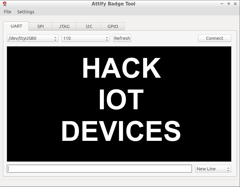
Here’s what the UART functionality in Attify Badge Tool does:
- Detects external USB devices connected to the system and adds them to the combo box on the top left corner of the GUI.
- Select the USB port where you have your device attached and the baudrate you want to use. If you’re unsure you can later on change the baudrate. How to connect over UART using Attify Badge tool
- After selecting the required baud rate, press enter to connect to the device. The connection status will be shown in the status bar on the bottom.The data received from the UART device will be printed on the black console window.You can use the edit box below it to interact with the device. The combo box on the bottom right corner allows you to chose the line terminator for each line that you send to the device.
2. SPI (Serial Peripheral Interface)
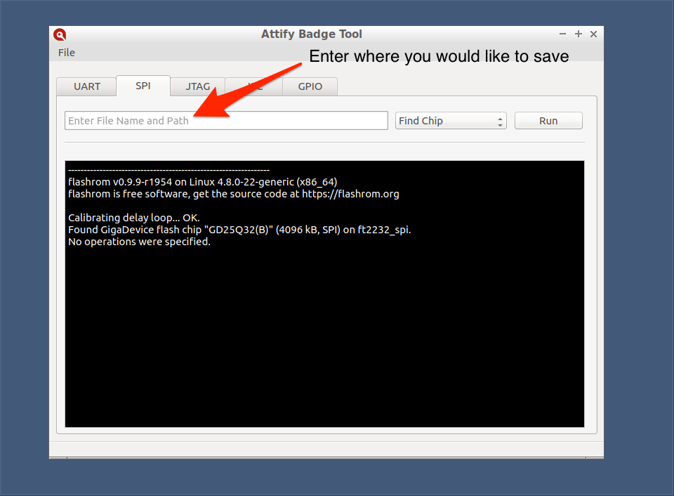
The SPI module is built on top of the popular `flashrom` command line tool. It allows users to detect, read, write and erase SPI based memory of the target device connected to the Attify Badge.
The usage is pretty straight forward.
- Select the required operation from the drop-down menu.
- In the case of read/write commands, specify a file path where the data will be stored or retrieved. An example path would be ~/files/firmware.bin. (https://blog.attify.com/content/images/2017/02/spi2.png)Firmware dumping using SPI
3. JTAG
The JTAG or the Joint Test Action Group is one of the most useful standards for exploiting a device. However, there is not a lot of publicly available information on this topic.
The JTAG module is built primarily using OpenOCD and GDB. This blog post does not go into the details of OpenOCD and GDB but a basic understanding of both is necessary to get the most out of the tool. In case you would like to learn JTAG Debugging and Exploitation, consider buying our self-learning JTAG exploitation kit available here.
2. SPI (Serial Peripheral Interface)>
The SPI module is built on top of the popular flashrom command line tool. It allows users to detect, read, write and erase SPI based memory of the target device connected to the Attify Badge.
The usage is pretty straight forward.
- Select the required operation from the drop-down menu.
- In the case of read/write commands, specify a file path where the data will be stored or retrieved. An example path would be
~/files/firmware.bin.
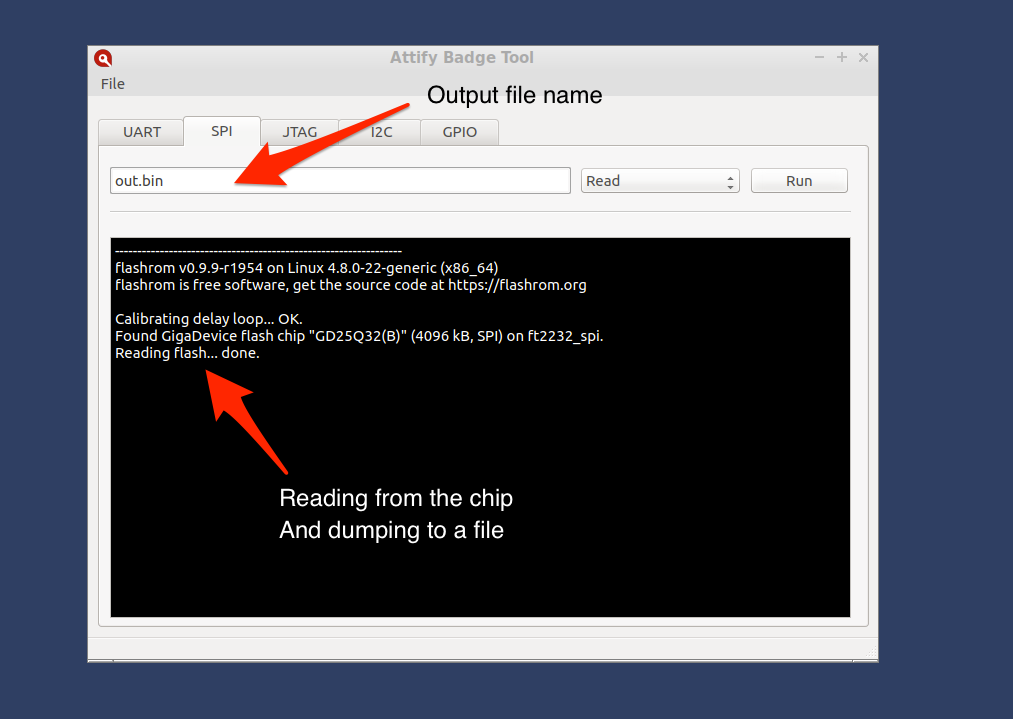 Firmware dumping using SPI
3. JTAG
The JTAG or the Joint Test Action Group is one of the most useful standards for exploiting a device. However, there is not a lot of publicly available information on this topic.
The JTAG module is built primarily using OpenOCD and GDB. This blog post does not go into the details of OpenOCD and GDB but a basic understanding of both is necessary to get the most out of the tool. In case you would like to learn JTAG Debugging and Exploitation, consider buying our self-learning JTAG exploitation kit available here.
Steps for JTAG Exploitation
-
Select the appropriate configuration file for your target device.The example used in the screenshot below shows the configuration file for the STM32 ARM MicroController. Custom configuration files can be added directly to the
cfg/directory. -
Click on Start OpenOCD Server. This will show the below screen.
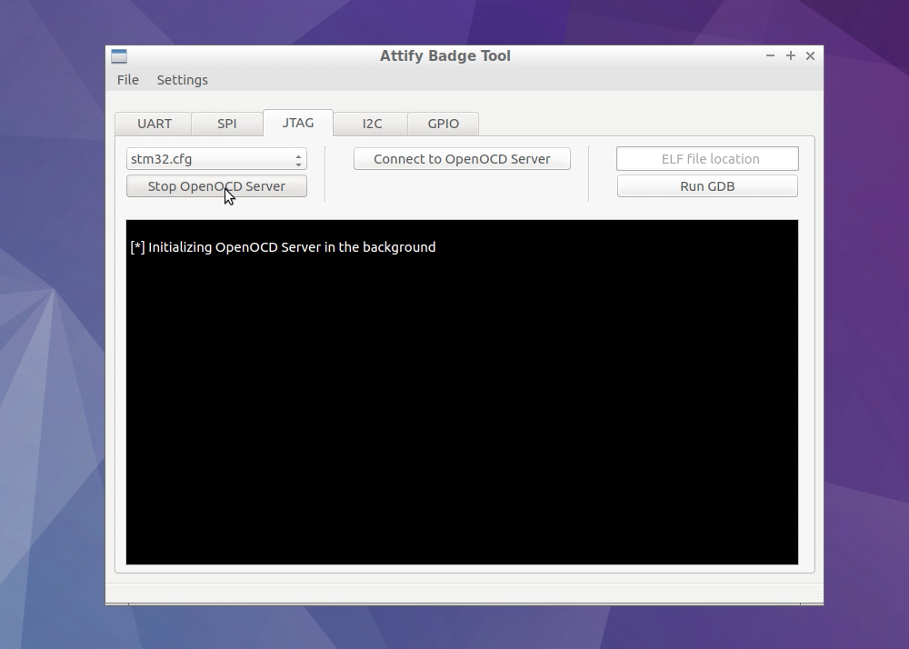
-
The next step is to connect to the OpenOCD server by clicking the “Connect to OpenOCD Server” button.This will launch a new terminal window with a telnet session connected to the OpenOCD Server.
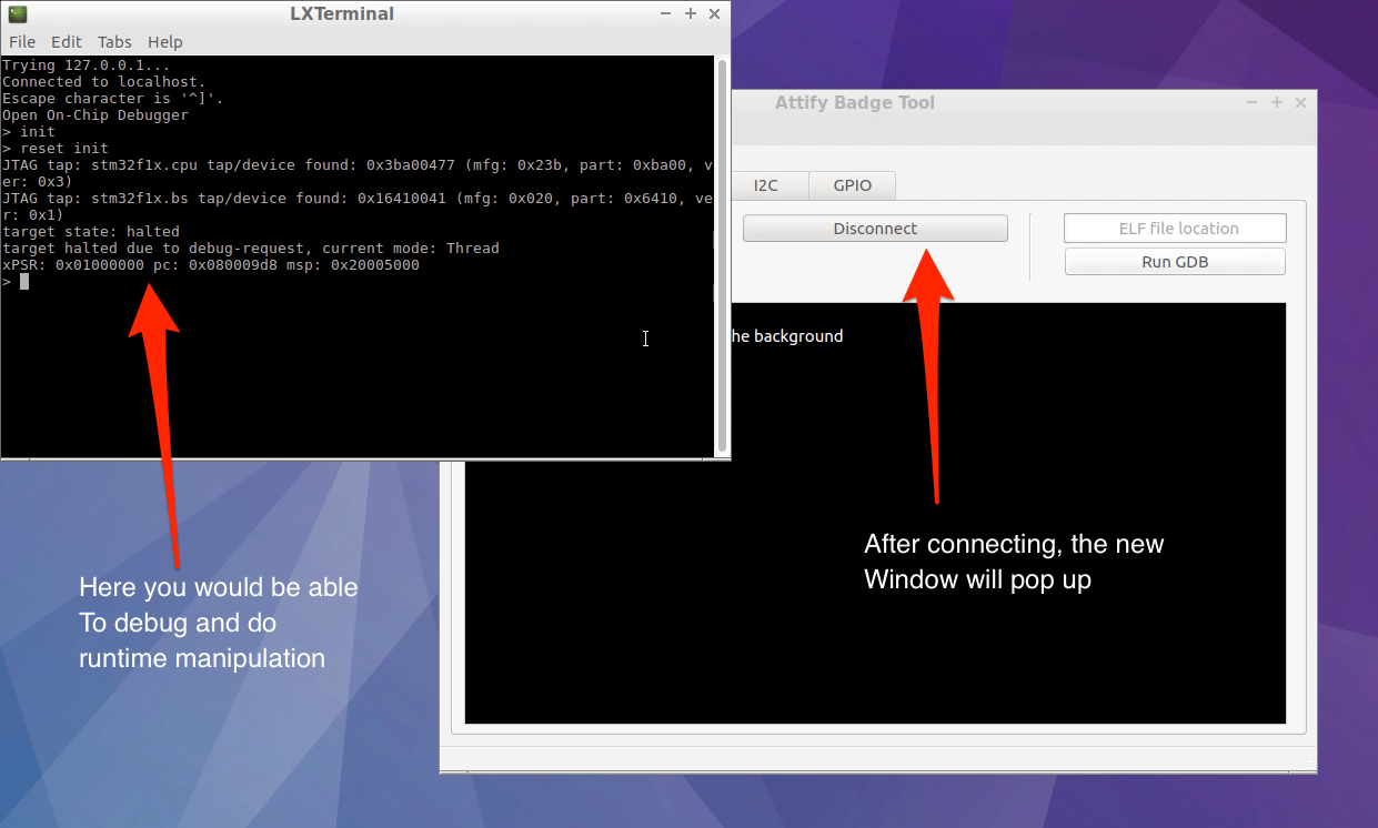 Debugging with JTAG and OpenOCD
 -
You can also use GDB in order to do further analysis – such as identifying and exploiting flaws in the firmware.To do this you need to have the corresponding elf file. Enter the path to the elf file in the path edit box and click on the “Run GDB“.This will launch a gdb session using which you can analyze the device.Never before has been using JTAG, OpenOCD and GDB so simple. I believe this gives you enough motivation to start using Attify Badge tool and hack IoT devices.
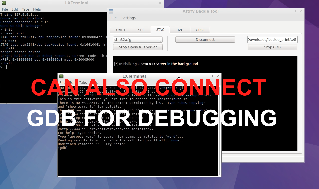 Connect GDB for JTAG debugging
4. I2C
The I2C module can be used to find I2C devices and to read, write and erase the contents of I2C EEPROMs connected to the badge.
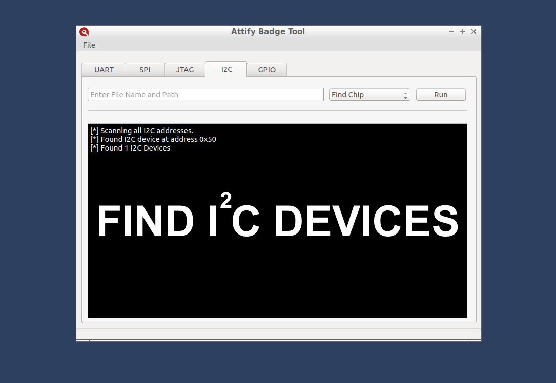 Find I2C devices using Attify Badge tool
In order to use it just select the required operation from the drop-down menu, enter the file path if required and click the “Run” button.
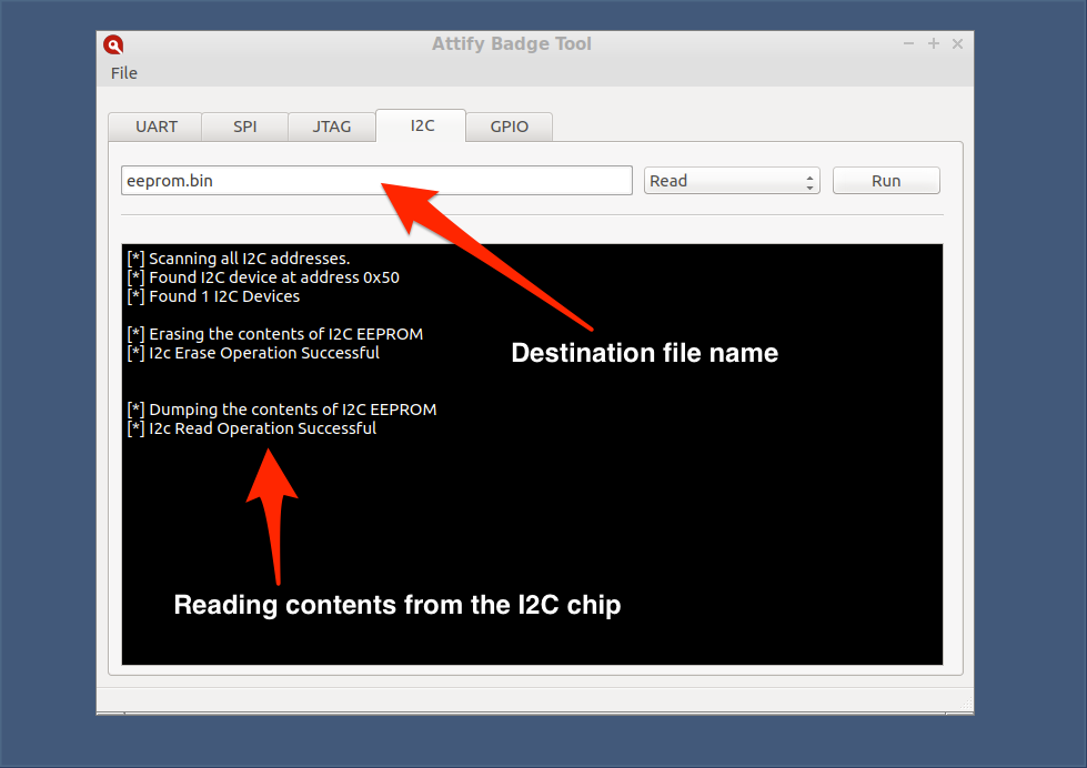 Dump contents from I2C chip
5. GPIO
The GPIO module allows users to use the pins D0 to D7 on the Badge as GPIO pins. If you are a hardware hacker or an electronics enthusiast, this would be typically interesting – because this allows you to extend the badge and maybe even connect your own additional devices to the badge.
To use, select the required mode ( Input / Output ) from the combo box next to the name of each pin.
Output Mode:
Checking the check box next to each pin will change the pin state to HIGH, un-checking the check box would change the pin state to LOW.
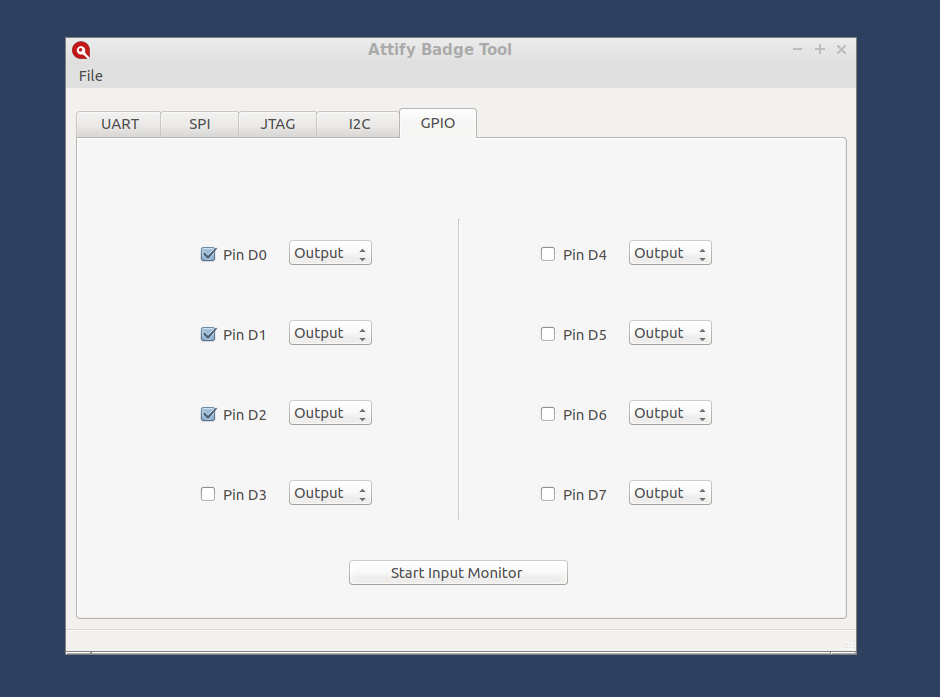
Input Mode:
In order to use the pins in input mode, change the modes of the required pins to Input, check them in order to activate the pins.
Click on “Start Input Monitor” to launch the Input Monitor Widget.
Click the start button on the Input Monitor Widget to start monitoring the input received to the selected pins.

Hack IoT devices and Pentest using the Attify Badge tool
The tool is Open Source and can be download from Attify’s Github Repository.
In case you don’t have an Attify Badge, you can purchase the badge here – Attify Store.
If you would like to learn IoT Security and Exploitation – all by yourself, you can get our IoT Exploitation Learning kit by clicking on the link below.
Conclusion
This is the first release of the Attify Badge Tool, and we have several improvements and features on our roadmap.
In case you have issues with the tool, or wish to have more functionalities added to the tool, feel free to create an Issue on the github repo or Contact the developers directly on the Github page of the tool.
Any contributions to the tool whether it’s code, bug reports or feature requests would be appreciated.