In this blog post, we are going to discuss how to generate some of the modulation types to send data from Arduino Nano and then receive it using GNUradio and GQRX to decode it to the original data sent.
Some of the things that we are going to cover in this post:
- Create various sorts of modulation using Arduino Nano (not Uno or others)
- Send data over 433MHz transmitter
- Capture the traffic using RTL-SDR
- Process it using GNURadio and Audacity to decode the modulation and recover the original data being transmitted.
In order to get started, we will need the following items:
Hardware
- Arduino nano
- 433MHz transmitter
- RTL-SDR
- Connecting Wires
Software
- Arduino IDE (https://www.arduino.cc/en/Guide/Linux)
- Gqrx (http://gqrx.dk/download/install-ubuntu)
- GNURadio-companion (https://wiki.gnuradio.org/index.php/InstallingGR)
- Audacity (http://ubuntuhandbook.org/index.php/2017/03/audacity-2-1-3-released/)
- Inspectrum(https://github.com/miek/inspectrum/wiki/Build)

Step1 : Create various sorts of modulation using Arduino Nano.
What is Modulation?
Modulation is nothing but a carrier signal that varies in accordance with the message signal .To know more what modulation is, let us understand the two major categories of modulation:-
- Analog Modulation
- Digital Modulation

Analog Modulation
In analog modulation, analog signal (Sinusoidal signal) is used as a carrier wave that modulates the message signal or data signal.

How analog modulation works?
A carrier wave has three defining properties,which are amplitude, frequency, and phase. These three defining properties are used to create three types of modulation:
- Amplitude Modulation
- Frequency Modulation
- Phase Modulation
Amplitude Modulation : In this type of modulation ,the amplitude of the carrier signal varies in accordance with the message signal, while other factors like phase and frequency remain constant.

Frequency Modulation : In this type of modulation,the frequency of the carrier signal varies in accordance with the message signal, while other factors like phase and amplitude remain constant.

Phase Modulation : In this type of modulation, the phase of the carrier signal varies in accordance with the message signal, while other factors like amplitude and frequency remain constant.


Digital Modulation
Digital modulation is somewhat similar to analog modulation except the carrier wave is of discrete amplitude signal. For binary signal, it has only two levels, either high, logic 1, low, or logic 0.
The modulation scheme is mainly of three types-
- ASK or Amplitude Shift Key
- FSK or Frequency Shift Key
- PSK or Phase Shift Key
Amplitude Shift Keying (ASK) : In this type of modulation, the amplitude of the carrier wave varies in accordance with the data signal. And if information is present, then it will be represented as 1 (high) else it will be always represented as 0 (low). This is also known as on and off keying.

Frequency Shift Keying (FSK): In this type of modulation, the frequency of the carrier waves varies in accordance with the data signal.

Phase Shift Keying (PSK) : In this type of modulation, the phase of the carrier signal varies in accordance with the message signal.

On and off Keying
Amplitude shift-keying (ASK) is a popular modulation technique used in digital data communication for a large number of low-frequency RF applications. The source transmits a large amplitude carrier when it wants to send a '1' and small amplitude carrier when it wants to send a '0' in its simplest form. On-off keying (OOK) modulation is a further simplification of this method, where the source sends NO carrier when it wants to send a '0'. In the simplest form, the presence of a carrier for a specific duration represents a binary one, while its absence for the same duration represents a binary zero.

We are going to transmit on and off keying modulated signal.
Step 2 : For sending this data, we have download the Arduino library for the RC_Switch, which contains the program for transmitting data on 433MHz from the URL – https://github.com/sui77/rc-switch
The source code can be downloaded here .
#include<RCSwitch.h>
RCSwitch mySwitch = RCSwitch();
void setup() {
    Serial.begin(9600);
 	mySwitch.enableTransmit(10); //Transmitter is connected to Arduino Pin 10
 }

void loop(){
	mySwitch.send("01100010000011000100000");
	delay(3000);
}
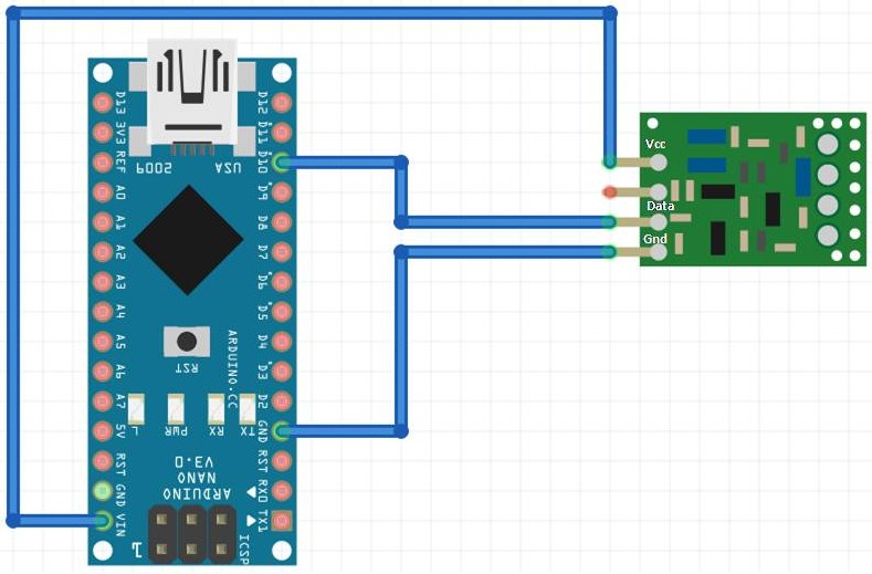
Step 3 : For sending the data over 433MHz, connect the 433MHZ transmitter with your Arduino.
This is how the Arduino connections would be overall –
Arduino 5V ⇐> VCC of transmitter
Arduino GND ⇐> GND of transmitter
Arduino D10 ⇐> Data of transmitter
Radio Signal Analysis : In the above we have already discussed about the modulation techniques, now we are going to analyze some radio signal. But, for signal analysis we need some hardware device to capture the radio signal and some software to display that signal.
HARDWARE
| Device | Function | Range |
|---|---|---|
| HackRF | RX/TX | 1MHz – 6Ghz |
| RTLSDR | RX | 24MHz-1766MHz |
| DX Patrol | RX | 100KHz-2GHz |
| USRP N-series | RX/TX | 1MHz-6MHz |
| BladeRF | RX/TX | 300MHz-3.8GHz |
| FUNcube | RX/TX | 150KHz-240MHz & 420MHz-1.9GHz |
| SDRPlay | RX/TX | 10KHz-2GHz |
| LimeSDR | RX/TX | 100KHz-3.8GHz |
| AirSpy Mini | RX | 24-1800Mhz |
In this blog we are going to use RTLSDR device.
SOFTWARE
- Gnu Radio Companion (GRC)
- GQRX
- SDR#,
- Inspectrum HDSDR,
- Linrad,
- Cubic SDR etc.
In this blog we are going to discuss Gnu Radio Companion (GRC),GQRX and Inspectrum HDSDR,
Step 4 : For capturing the traffic using RTL-SDR, we need to install the Gqrx.
Open the terminal and type
sudo apt-get install gqrx-sdr
Once done, plug the SDR device and type
lsusb
RTL-SDR is a very cheap dongle that can be used as a computer based radio scanner for receiving live radio signals in your area. Depending on the particular model it could receive frequencies from 24 MHz up to 1766 MHz.
Quoting Wikipedia GQRX is an open source software defined radio (SDR) receiver implemented using GNU Radio and the Qt GUI toolkit. Currently it works on Linux and Mac with hardware supported by gr-osmosdr, including Funcube Dongle, RTL-SDR, Airspy, HackRF, BladeRF, RFSpace, USRP and SoapySDR.

Step 5 : Now open the Gqrx software by typing gqrx in terminal and configure the I/o. In the device menu, select the device and then click ok.

Step 6 : Set the frequency at 433mHz (transmitter frequency).

Step 7 : Click on the start button for capturing the traffic.

By using gqrx, you will get to know the actual frequency of your transmitter which will always be with in the range of 432-433 MHz .
Step 8 : For processing the signal, we now need to install the Gnuradio companion.
Open the terminal and type
sudo apt-get install gnuradio
Quoting wikipedia GNU Radio Companion (GRC) is a graphical tool for creating signal flow graphs and generating flow-graph source code.
Step 9 : Once done, open the grc software by typing gnuradio-companion in terminal.
Draw the block diagram and change the sampling frequency.Now, click on Run for recording the signal and further change the frequency and sample rate.
The grc file can be downloaded here.
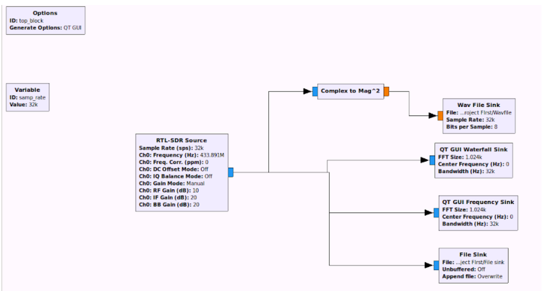
Waterfall plot and FFT sink

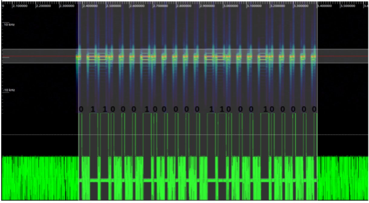
Step 10 : Download the Audacity for demodulating the signal. Once it’s done, open the wav file and start decoding. You will now get the actual signal which was transmitted.
Download the wav file sink here.

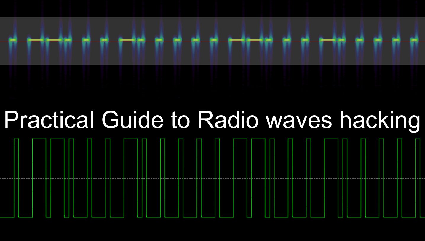
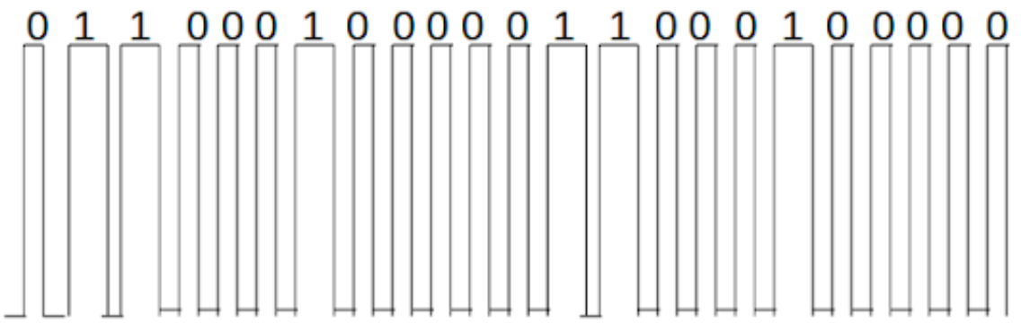
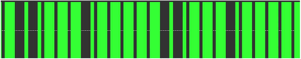
We have finally recovered the original on and off keying signal. We have transmitted 0 for a short duration of time and 1 for a longer duration of time.
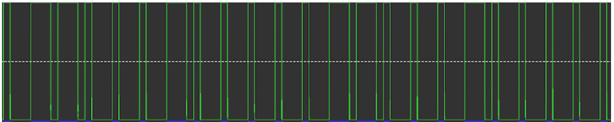
Step 11 : Install the inspectrum for demodulating the signal. Once it’s done, open the file sink file and start decoding.
Download hex file from here.
Quoting wikipedia Inspectrum is a tool that can be used for analysing captured signals, primarily from software-defined radio receivers.that's basically used for measure the time period, symbol rate, symbol period, etc.
Sampling Plot : In the sampling plot, we can measure the number of samples/message bits that are transmitted by the source.
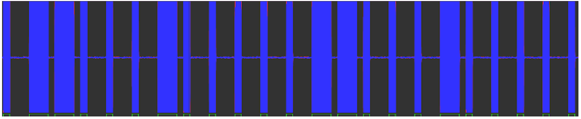
Frequency Plot : In the frequency plot, we can measure the time period and frequency of the signal.
Amplitude Plot: In the amplitude plot,we can measure the amplitude of the signal.
That’s all, folks! In case of queries, reach out to us at https://www.attify.com/contact-us/